Since I started to build my quadcopter, I was looking for a more organic way to control this flying model. Normally to fly models, people uses sophisticated remote controllers that can handle every capability of the flight controller/model. But even if a radio controller is the best thing you can have to fly, this is not the best way to ‘feel’ your flight, but the Glove Controller is!
Before a long speech, let’s start with the glove in action!
How everything happened.
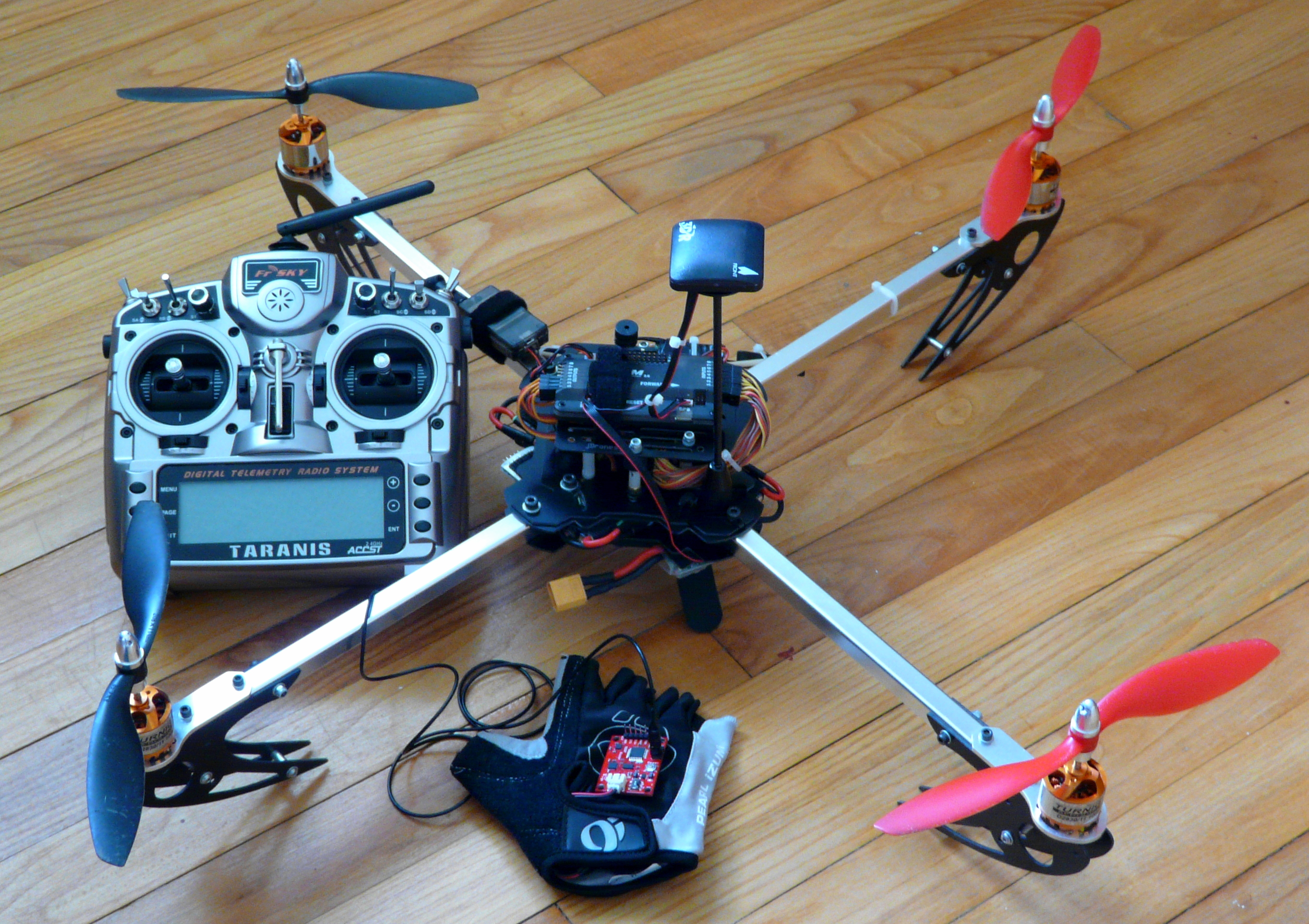
I was flying my quadcopter with my new FrSky Taranis radio, and was thinking about how awesome is the trainer port to share your passion (and your copter) with someone else. Thanks to this feature, you can share the control of your model with a buddy’s radio. Thinking about that, I realized that the trainer port could be used for other purpose than training… Actually it could be used with everything that can send a PPM (Pulse-Position Modulation) signal to the radio…
This is how the Glove Controller was born!
What is that?
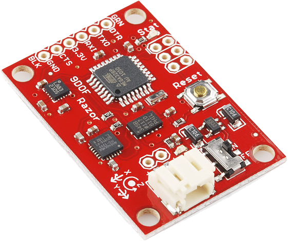
I called this project The Glove Controller because of the final form factor, but I should name it “The 9 DoF IMU Controller” which is incomprehensible but so much sexier, isn’t it? Okay, let’s expand these acronyms to make sense: The 9 Degree-of-Freedom (DoF) Inertial Measurement Unit (IMU) Controller. The IMU is something so common now, everybody has one in its pocket. No? Doesn’t sound familiar to you? Come on! People commonly calls that a smartphone or a tablet! I didn’t say that a smartphone is an IMU, did I? No, but smartphones and tablets embed an accelerometer and a gyroscope to detect motions, and a magnetometer to detect magnetic field (basically used by compass). This combo of accelerometer + gyroscope + magnetometer is an IMU.
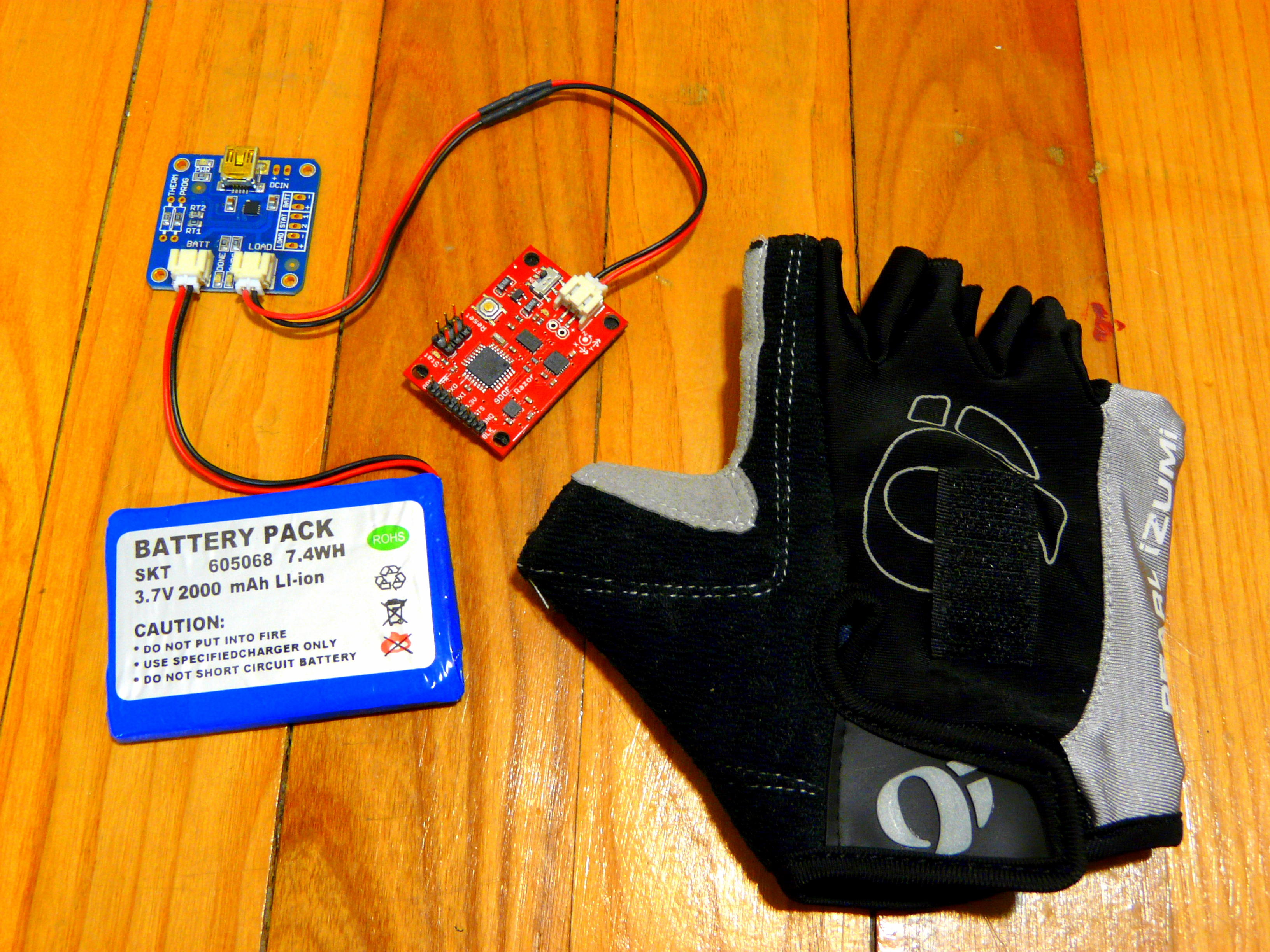
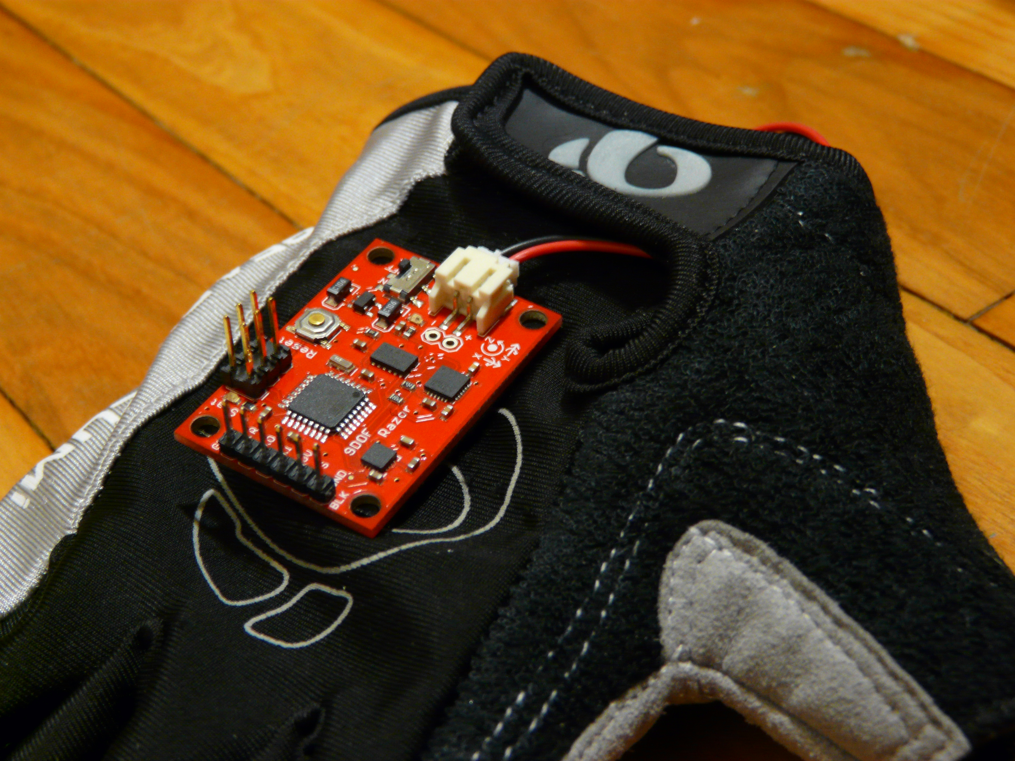
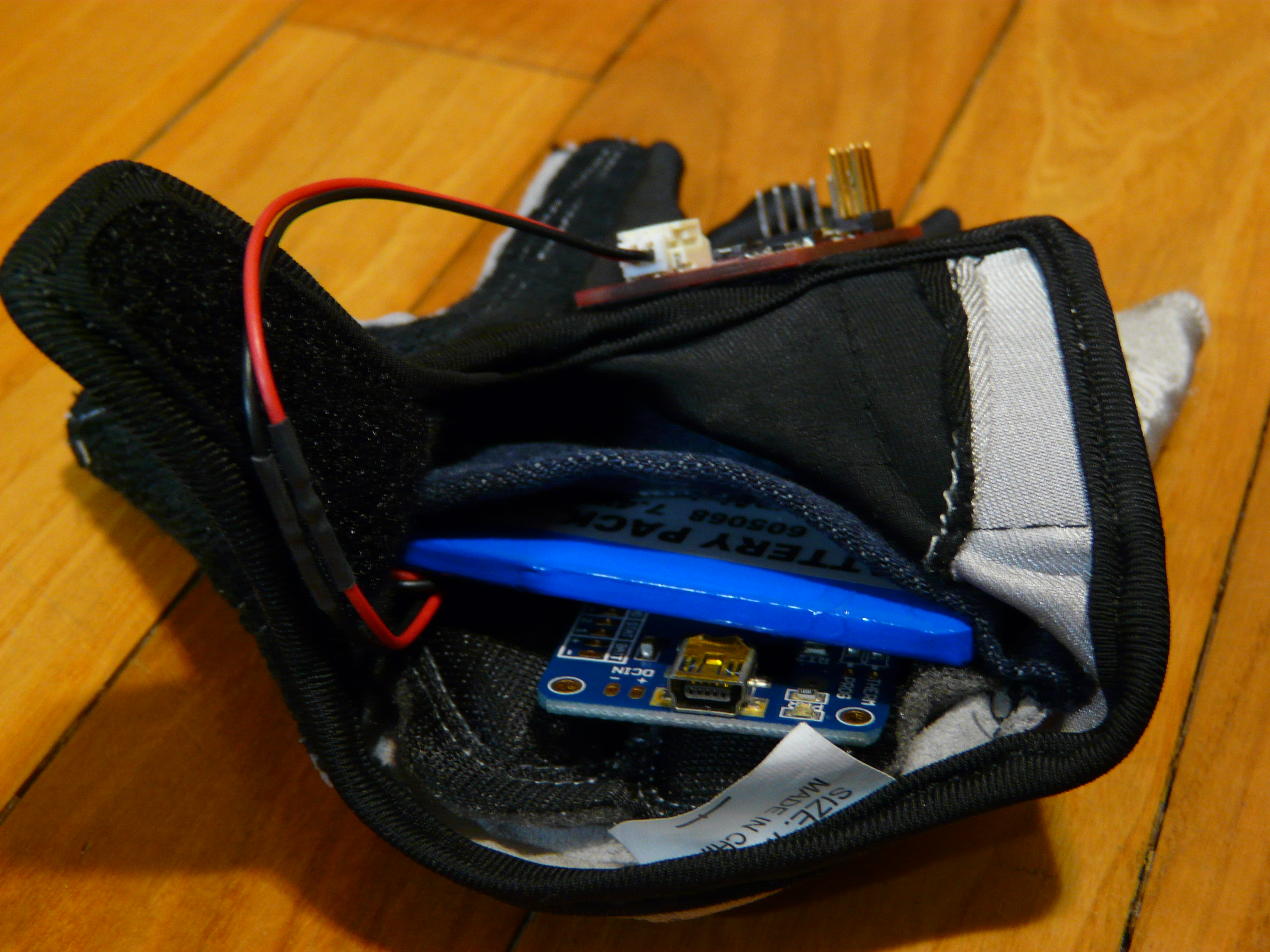
The one I used for the glove features a 3-axis accelerometer, a 3-axis gyroscope, and a 3-axis magnetometer which gives the 9 degrees of freedom. The IMU is powered by a 3.6V lithium-ion battery of 2Ah and an USB charger to charge the battery. The glove itself is a pretty basic half-finger cycling glove.
How it works.
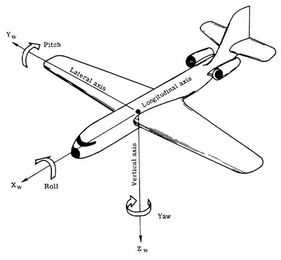
The IMU 9DOF Razor comes with an awesome firmware that combines every sensor outputs to give the roll, pitch and yaw which are the 3 basic movements of an aircraft. What a coincidence, this is exactly what I need to control my model on the (x, y) plan. I guess that some people have noticed, I didn’t mention the throttle, which is, actually, a very important point to fly. But with the complexity of current flight controllers, I’m sure that the mode ‘Altitude Hold’, used to keep a constant altitude, is pretty common, so no need of throttle! The quadcopter will keep the targeted altitude by itself when the glove is in use.
And you know what, I’m going to simplify that again by removing the yaw. My flight controller, which is an APM2.6 with Arducopter, has a mode called ‘Super Simple Mode’ that allows the pilot to control the movement of the copter from the pilot’s point of view regardless of which way the copter is facing. I hope that’s clear, because it’s complicated to find a better explanation about the benefit of this mode, I think you need to fly a model once to truly understand… but this video can give you some insights.
Here is it! The Altitude Hold locks the z-axis and takes care of the throttle, and the Super Simple Mode takes care of the yaw for us. So now, the glove just has to handle the Pitch and Roll. Damn I love that board!
Here is how the glove works
- The IMU on the glove sends the Pitch and Roll as a PPM signal to the radio transmitter via the trainer port.
- The radio transmitter reads the signal and sends that to its receiver.
- The receiver on the copter send the data to the flight controller.
- The Pitch and Roll data are processed by the flight controller.
- The motor speed controller outputs are changed according to the Pitch and Roll.

The technical part.
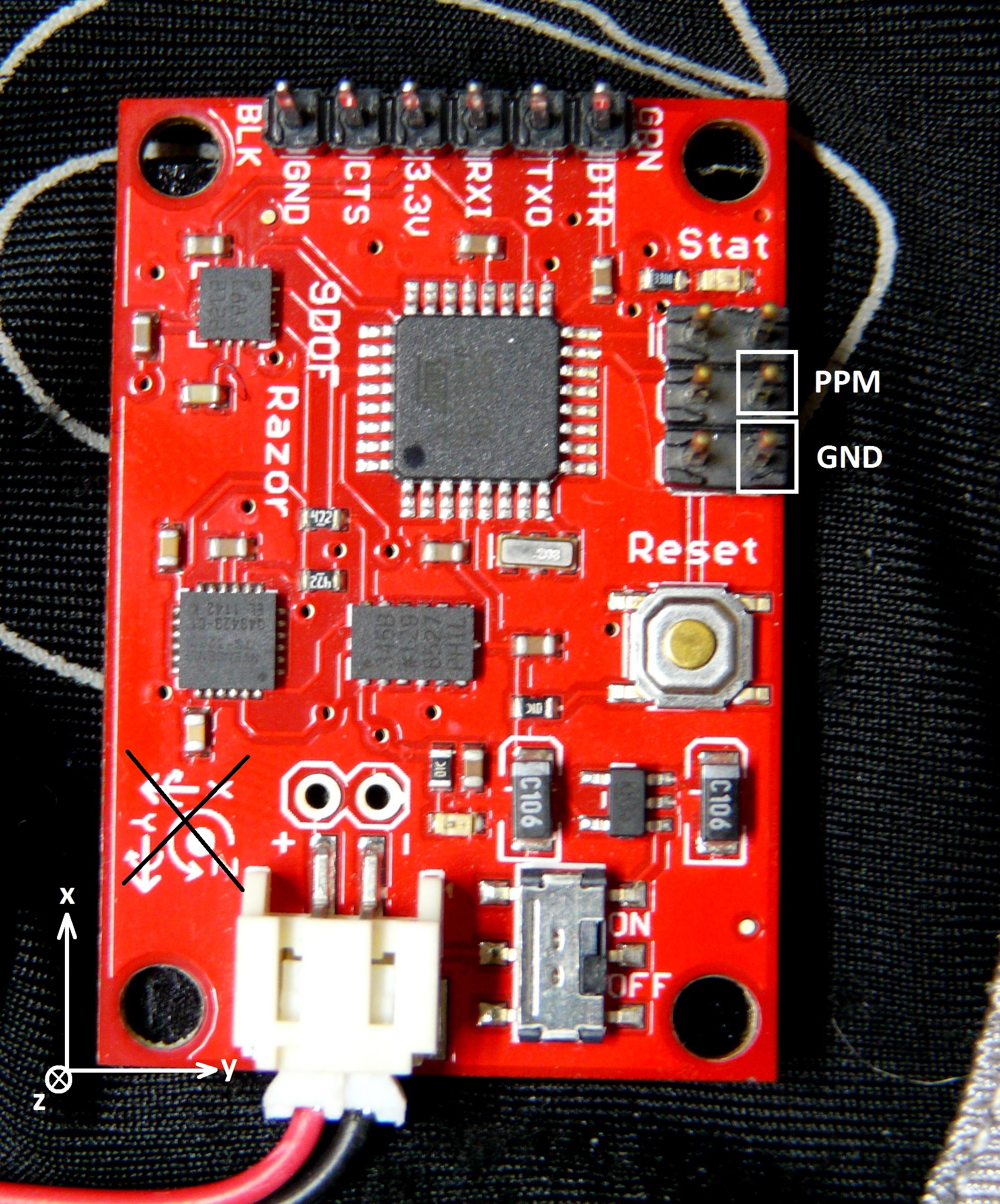
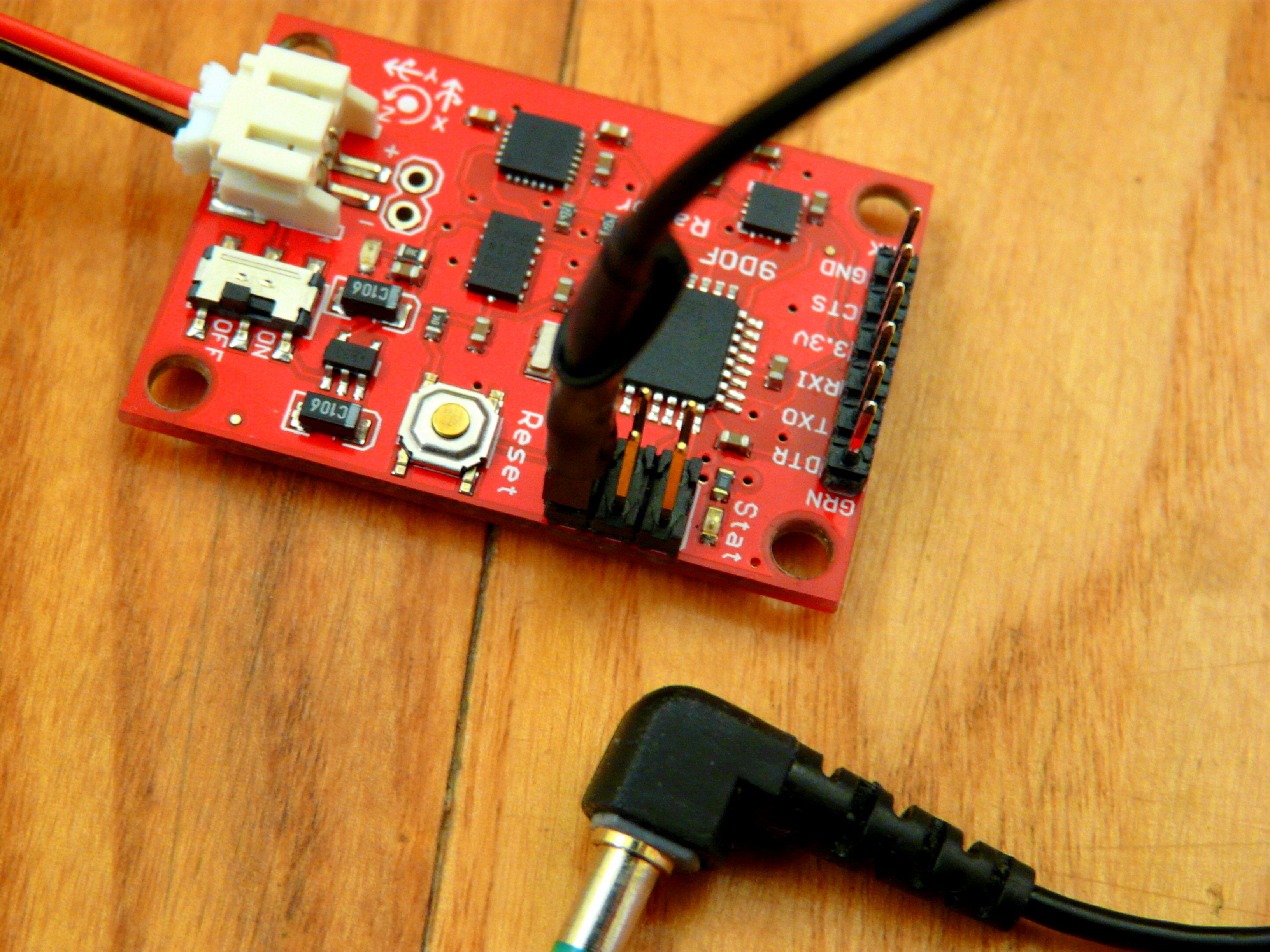
The IMU 9DOF Razor is designed with an Atmel microcontroller, the ATmega328P, and so Arduino compatible, which means you just need a 3.3V Serial-to-USB breakout to flash the board. I use the Sparkfun one that matches the board pinout. I modified the original firmware on the IMU in order to add the PPM functionality and to cap the pitch and roll outputs.
Basically the board gives an angle between [-180, 180] degree, but the radio understands a range of [-100, 100] %. So I capped the maximum angle to [-90, 90] degree for pitch and roll, because you don’t want to twist your wrist to ±180 deg. However the roll becomes super sensitive when the pitch goes beyond ±85 deg, so the pitch is capped at ±85 deg while the roll is capped at ±90 deg. I added a handy protection if something goes wrong or if you need your hand, then you just have to move your hand beyond 110 deg (palm facing the sky) and every output is forced to zero, so the copter should stay still. The outputs are frozen until your palm is facing the ground again (= pitch and roll are below 10 deg).
The PPM is generated by the internal 16-bit timer of the microcontroller which means while the PPM is running, the microcontroller is still processing sensor data. Thus there is no latency that could be involved by using delays. My implementation was inspired by the great PPM example from here. By the way, just a word about PPM; most of the time, people thinks that PPM is like PWM which is Pulse Width Modulation, but it’s not. PPM is a form of digital modulation like FSK and PSK (Frequency and Phase-Shift Keying), so each pulse width represents one byte, and each pulse width is different from each other, which is not the case with a PWM signal. To make it clearer, let’s say that with PPM, you can send the value of multiple channels, and with PWM, you can send the value of only one channel (but at a higher frequency).
The build part.
What do I need to fly with the glove?
- A [what you want]copter, could be a tri, quad, hexa, octo, or any other variant.
- A flight controller with Altitude Hold mode or equivalent, and if you can have the Super Simple Mode, it’s better.
- A radio transmitter with a master trainer port. Note that a slave trainer port won’t work!
- An IMU 9DOF Razor + a 3.6V battery (+ a FTDI Serial-USB 3.3V breakout to program the board).
- A jack 3.5mm connector + cable.
- A glove of your choice.
Set up the IMU
Prerequisite: Shall know how to use Arduino IDE and how to program a board.
- Solder the male headers.
- Flash the original firmware: ptrbrtz/razor-9dof-ahrs
- Follow this tutorial to calibrate the board (very important!).
- Save the calibrated offsets and copy them in the mod version: eklex/GloveController
- Flash the IMU with the mod version.
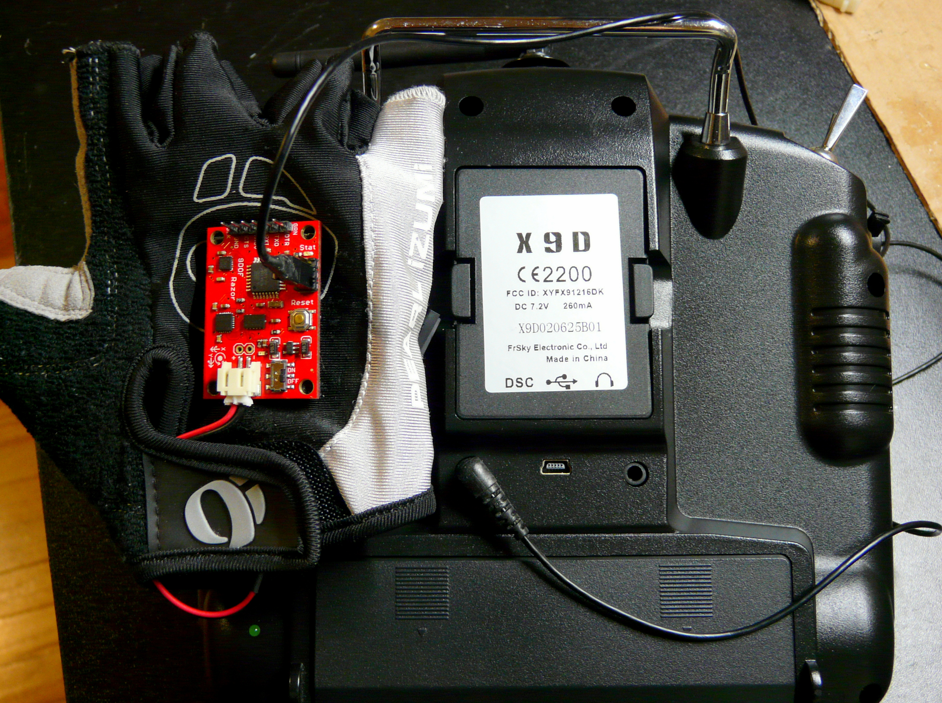
- Put the IMU on top of the glove held with a piece of velco tape, and the battery inside of the glove.

Create the radio-IMU cable
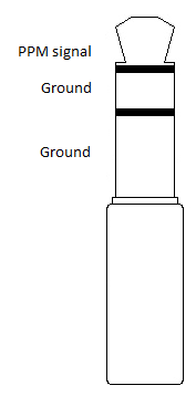
Note: This step was tested on a FrSky Taranis radio transmitter, I cannot guarantee it’ll work on yours. So check the user manual or RC forums to find the right trainer port pinout. It’s also possible that your radio does not use a 3.5mm jack for the trainer port.
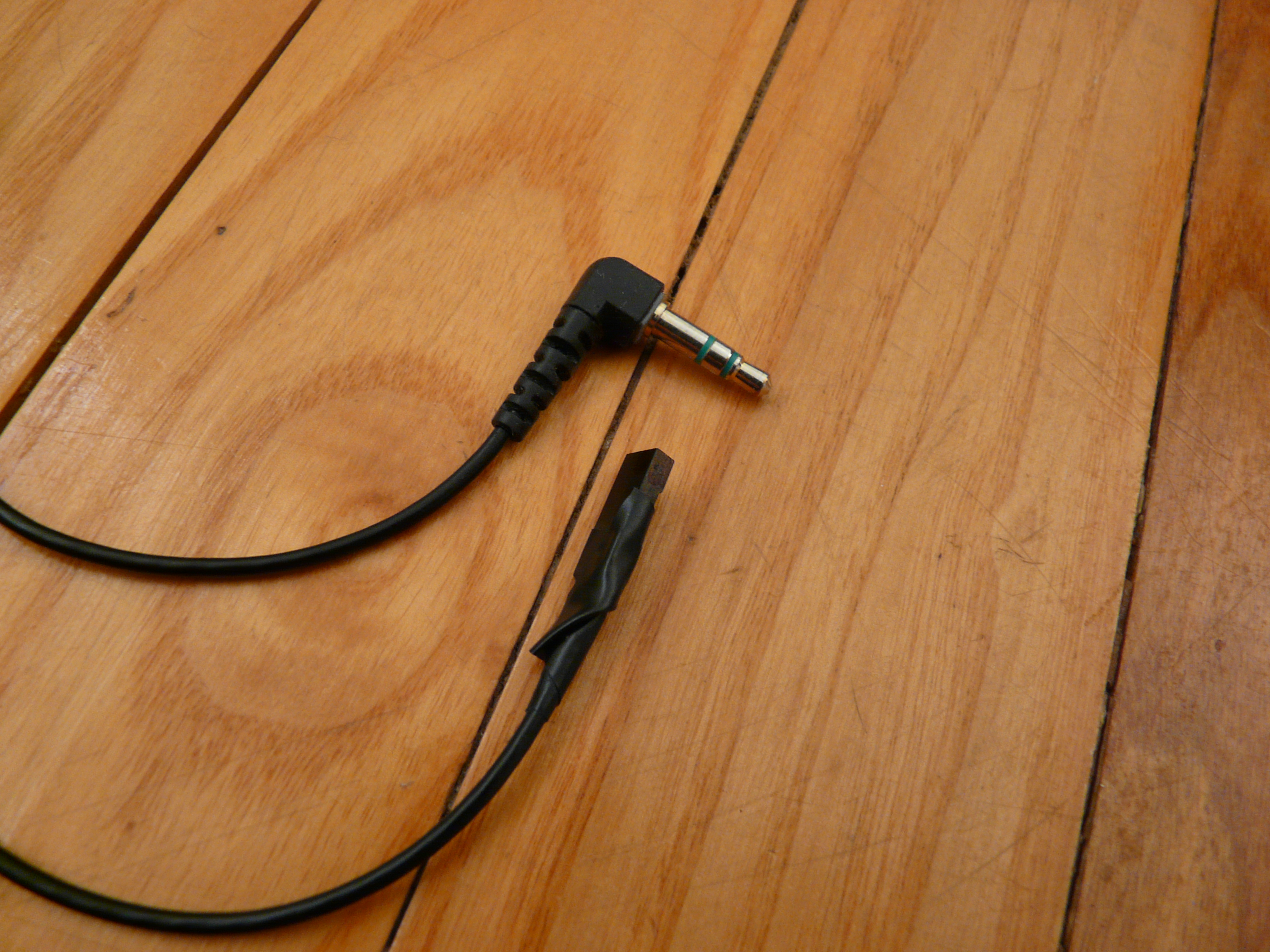
- Find an old earplug cable with a 3.5mm jack.
- Remove the earplugs, keep the cable and the jack.
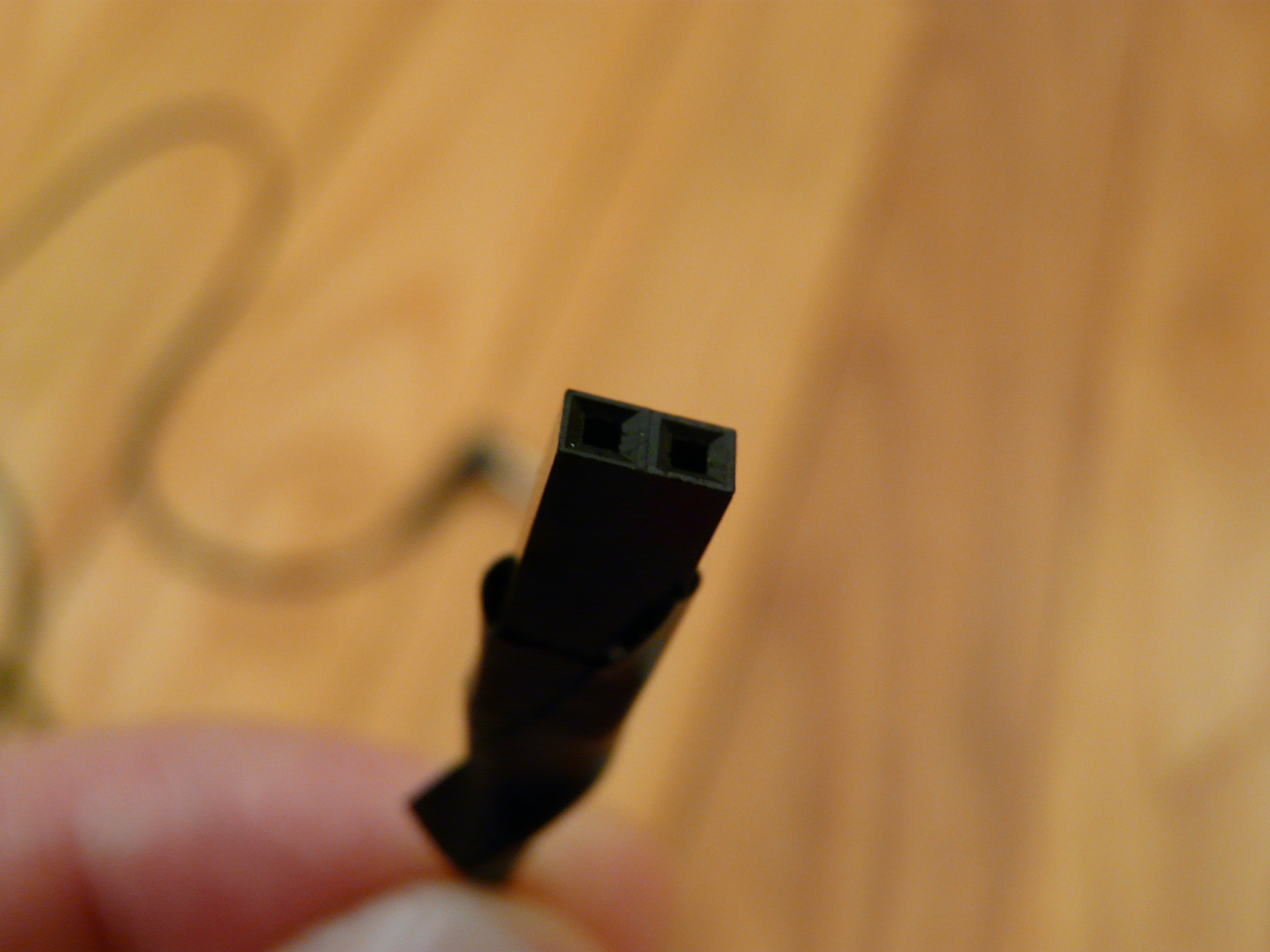
- Use a 2-pin female header and solder the cable according to the pinout below.
Connect the glove and the trainer port
- Connect the 2-pin female header on the header just above the reset button. The ground is on the edge of the board and close to the reset.
- Plug the jack on the DSC/trainer port of your radio.
Setting the radio transmitter to enable the trainer port
- If you have a non OpenTX radio, please see your user manual.
- Otherwise, long press on menu, go to the TRAINER page.
- If you trust your hand, set Ail and Ele to 100%, otherwise start with 50% as a test.
- Lay the glove flat on a table to have roll and pitch null.
- Reset the IMU, and wait 5 sec, put the IMU upside down to force every output to zero.
- Press on Cal to reset every trainer channel.
- Put your IMU at 90 deg, you should have a full ±100% on one channel, if it’s not the case then increase the Multiplier to have ±100%.
- (Optional) To understand how the trainer mode works on OpenTX radio, you can watch the video below. An example of a trainer configuration is shown.
Take-Off!
You are ready to go! Let’s fly!
Next improvements: Shall add a wireless connexion between the IMU and the radio, may add the throttle to increase the fun. Stay tuned!